The basis of both principles is the sine wave of the mains voltage.
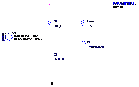
Sine wave dimmer schematic.
The circuit complies with the iec55551 norm.
The light bulb goes out.
Then the gate of triac gets the current fast too.
When resonance is achieved and it can be through an lc circuit the output signal will be a sine wave because a sine wave represents resonance.
The current flows to charge c1 slowly.
If you measure the voltage with a common meter it will likely read a lower voltage because the meter is performing rms calculations for you but this isn t the whole story.
The max load it can handle is 400va.
At a frequency of 50 hz the voltage changes its polarity 100 times per second.
The current charges to c1 faster.
So with an lc network we re able to resonant the square wave produced by the 555 timer chip into a sine wave.
The dimmers high switching frequency reduces the size of the passive filter compo nents and insures that any acoustic noise produced within the dimmer is well above the audible range.
And the gate of triac will get a current slowly.
In contrast we adust vr1 is low resistance.
4 in dimmers that chop the sine wave such as scr or ssr dimmer the lights would hum the loudest when dimmed to 50 because sine waves peak half way through their cycle as the reach their crest and begin returning to 0v.
In mathematics a sine wave is the perfect model representation of resonance.
A dimmer is a phase angle power reducing circuit which essentially chops the sine wave to deliver less effective power to the load.
So at the load is a quite full.
Such a circuit is often found on cheap commercial light dimmers and is proven to work reliable for the rated power.
But the ac main runs faster.
This peak half way through the wave forms means that the amplitude difference between on and off is greatest when the dimmer is set to 50 and therefore the harmonics for.
In order to use the full half sine wave of the rectified mains voltage tha time constant can be adjusted from for example 0ms to 9 ms approximately half of the full wave period in the case of a 50hz mains system.
Inductive load in a the same circuit even if the dimmer is suitable for both load types.
A b c d e f g h j k a b c d e f g h j k file name.
For instance triacs are extremely widely used dimmer switch applications where the circuit is made to make the device switch in this way that it performs only for a specific portion of the ac sine wave and remains cut off during the leftover parts of the sine wave.
The circuit is working by controlling the phase of the 220vac voltage allowing the load to be powered for less than 360º of the full sine wave.
Sinewave dimmer dsn main schematic 3 03 2010 christophe theuwissen path.
It therefore also reaches the zero crossing point at which there is freedom from both current and.

